Mnemonic
| A |

Description
The basic purpose of this instruction is to add two 16-bit operands. One of the operands must first be loaded into the accumulator, such as by means of execution of a load-accumulator instruction. The add instruction then provides the address of the other operand, which must be in main storage. Addition takes place, and the result is placed in the accumulator:
(Sign bit 0 = 0 specifies + number.)
 0 000 0000 1001 1101   =    Contents of accumulator
+0 000 0010 0011 0101   =    Contents of storage location addressed by add instruction
 0 000 0010 1101 0010   =    Result loaded into accumulator
Although the result replaces the contents of the accumulator, the contents of the addressed storage location remain unchanged.
The result of the addition is either positive or negative, depending upon the magnitude of the values used and whether the signs of the two operands are the same:
+ plus a + = + - plus a - = - + plus a - = sign of the larger operand - plus a + = sign of the larger operandThe value in the accumulator is positive if the leftmost bit is at a value of 0; the value in the accumulator is negative if the leftmost bit is at a value of 1. Negative numbers are in two's-complement form.
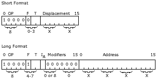
There are no addressing exceptions for the add instruction; all forms of addressing that are described under "Effective-Address Generation" apply to the A instruction.
Indicators: The carry indicator is automatically reset to 0 at the beginning of an add-instruction execution. If, during the add-instruction execution, a carry-out of the high-order (leftmost) position of the accumulator occurs, then the carry indicator is set to 1; if no such carry-out of the high-order position occurs, the carry indicator remains at its reset condition of 0. It can subsequently be set or reset by the various actions listed under "Carry and Overflow Indicators" (see Figure 13).
The overflow indicator must be reset to 0 if it is to be used during execution of an add instruction. If the overflow indicator is at a value of 1 at the start of an add operation, it is not changed regardless of the result of the add operation. If the overflow indicator is at a value of zero at the start of an add operation, it is set to a value of 1 if the addition produces a result that exceeds the capacity of the accumulator. For example, when the following two 16-bit operands are added together,
 S

 0 100 0000 0000 0000        Operand in accumulator -- a positive number
+0 100 0000 0000 0000        Operand in main storage -- a positive number
 1 000 0000 0000 0000   =    Result in accumulator -- a negative number
(S = Sign bit)
the result is greater than the capacity of the accumulator because the accumulator specifies a negative result (the leftmost bit is at a value of 1). In this case, the overflow indicator is set to 1. The carry indicator, however, is not set to one because a carry-out of the high-order position of the accumulator does not occur. Refer to "Carry and Overflow Indicators" for a discussion of how these two indicators can be used together in certain arithmetic operations.
The maximum capacity of the accumulator is:
| Power-of-2 Notation | Decimal Notation | Hexadecimal Notation |
|---|---|---|
| +215-1 | +32,767 | +7FFF |
| -215 | -32,768 | -8000 |
Examples
Add
| Assembler Language Coding | Hexadecimal Value | Description of Instruction | |||||||||
|---|---|---|---|---|---|---|---|---|---|---|---|
| Label | Operation | F | T | ||||||||
|
|
32 | 33 | 35..40.. | |||||||
| A | DISP | 80XX | Add contents of CSL at EA (I+DISP) to A | ||||||||
| A | 1 | DISP | 81XX | Add contents of CSL at EA (XR1+DISP) to A | |||||||
| A | 2 | DISP | 82XX | Add contents of CSL at EA (XR2+DISP) to A | |||||||
| A | 3 | DISP | 83XX | Add contents of CSL at EA (XR3+DISP) to A | |||||||
| A | L | ADDR | 8400XXXX | Add contents of CSL at EA (Addr) to A | |||||||
| A | L | 1 | ADDR | 8500XXXX | Add contents of CSL at EA (Addr+XR1) to A | ||||||
| A | L | 2 | ADDR | 8600XXXX | Add contents of CSL at EA (Addr+XR2) to A | ||||||
| A | L | 3 | ADDR | 8700XXXX | Add contents of CSL at EA (Addr+XR3) to A | ||||||
| A | I | ADDR | 8480XXXX | Add contents of CSL at EA (V in CSL at Addr) to A | |||||||
| A | I | 1 | ADDR | 8580XXXX | Add contents of CSL at EA (V in CSL at "Addr+XR1") to A | ||||||
| A | I | 2 | ADDR | 8680XXXX | Add contents of CSL at EA (V in CSL at "Addr+XR2") to A | ||||||
| A | I | 3 | ADDR | 8780XXXX | Add contents of CSL at EA (V in CSL at "Addr+XR3") to A | ||||||
But wait, there's MORE...