 0
0
Mnemonic
| SLC |

Description
The purpose of this instruction is to shift the contents of the accumulator and accumulator extension left, a bit at a time, as if these two registers made up a single 32-bit register. Zeros are shifted into position 15 of the accumulator extension and then to the left in order to fill vacated positions. Bits shifted out of accumulator-extension position 0 are shifted to the left into accumulator-position 15. Execution of the shift-left-and-count-accumulator-and-extension instruction stops when:
Location of the shift count is specified by the T bits of the instruction as follows:
| T Bits (6 and 7) | Shift Count Location | |
|---|---|---|
| 01 | Low-order six bits in index-register 1 | |
| 10 | Low-order six bits in index-register 2 | |
| 11 | Low-order six bits in index-register 3 |
Note: When the T bits are 00, the shift-left-and-count-accumulator-and-extension instruction is executed in exactly the same manner as a shift-left-accumulator-and-extension instruction (SLT) with its T bits set to 00.
When execution of a shift-left-and-count-accumulator-and-extension instruction starts, the shift count is automatically moved from the specified index register to CPU circuits that do the counting. When the operation is ended, the specified index register is updated as follows:
| Index-Register Bits | Condition at End of Operation | |
|---|---|---|
| 0-7 | Unchanged | |
| 8 | Reset to 0 | |
| 9 | Reset to 0 | |
| 10-15 | Contain residual count |
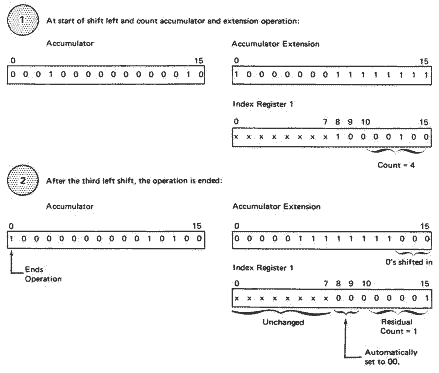
If the count is decremented to zero before a 1 is shifted into accumulator-bit 0, the residual count is 0. If a 1 is shifted into accumulator-bit 0 before the count is decremented to 0, the operation is ended. The residual count value is loaded back into the index register. For example:

In this example, the initial count is 4, but after three shifts have occurred, a 1 is in accumulator-position 0. This condition ends the operation. Three shifts have occurred, so the residual count stored into the index register is 1 (4 - 3 = 1).
If the shift count is initially zero, the instruction performs as a no-operation, regardless of the value of accumulator-bit 0. In this case, no shifting occurs, the carry indicator is not changed, and none of the bits in the specified index register are altered.
If accumulator-bit 0 is initially at a value of 1 and the initial count does not equal zero, the carry indicator is turned on. Also, bits 8 and 9 of the specified index register are reset to 00, but the count is not changed. Again, shifting does not occur.
Core storage is not addressed during execution of a shift-left-and-count-accumulator-and-extension instruction.
Indicators: The carry indicator is set or reset differently for the shift-left-and-count-accumulator-and-extension instruction than it is for the shift-left-accumulator-and-extension instruction. The carry indicator can have the following values after execution of a shift-left-and-count-accumulator-and-extension instruction:
| Count | Accumulator Bit 0 Equals | Carry Indicator Equals | |
|---|---|---|---|
 0 0 |
1 | 1 | |
| = 0 | 1 | 0 | |
| = 0 | 0 | 0 |
The carry indicator is set or reset by bits shifted out of accumulator-bit 0 in the shift-left instruction but not in the shift-left-and-count instruction. In the shift-left-and-count operation, the carry indicator is affected as shown in the immediately preceding table.
If, however, the T bits in a shift-left-and-count-accumulator-and-extension instruction are 00, the carry indicator is affected exactly as described in the shift-left-accumulator-and-extension instruction description.
The overflow indicator is not affected by the shift left and count accumulator and extension operation.
Examples
Shift Left and Count Accumulator
| Assembler Language Coding | Hexadecimal Value | Description of Instruction | |||||||||
|---|---|---|---|---|---|---|---|---|---|---|---|
| Label | Operation | F | T | ||||||||
|
|
32 | 33 | 35..40.. | |||||||
| SLC | DISP | 10*X | Contents of A and Q shift left the number of shift counts in DISP | ||||||||
| SLC | 1 | 11C0 | Contents of A and Q shift left the number of shift counts in XR1 unless 1 bit shifts into accumulator position 0 | ||||||||
| SLC | 2 | 12C0 | Contents of A and Q shift left the number of shift counts in XR2 unless 1 bit shifts into accumulator position 0 | ||||||||
| SLC | 3 | 13C0 | Contents of A and Q shift left the number of shift counts in XR3 unless 1 bit shifts into accumulator position 0 | ||||||||
For the four examples below, assume that the index register was previously loaded by an LDX instruction. Only the low-order bit positions (10-15) of the index register (XR) are shown and only the high-order bit positions (0-5) of the accumulator (A) are shown. Those bit positions containing an X can be 0 or 1.
| Example Number | 1 | 2 | 3 | 4 |
|---|---|---|---|---|
| XR before SLC | 000011 | 000100 | 000101 | 000110 |
| XR after SLC | 000000 | 000000 | 000001 | 000010 |
| A before SLC | 00001X | 00001X | 00001X | 00001X |
| A after SLC | 01XXXX | 1XXXXX | 1XXXXX | 1XXXXX |
| Carry indicator after SLC | OFF* | OFF* | ON** | ON** |
Yes, the ** note in the last table really says "SLCA" in the original document. That is not an error on my part. -- HSS
But wait, there's MORE...