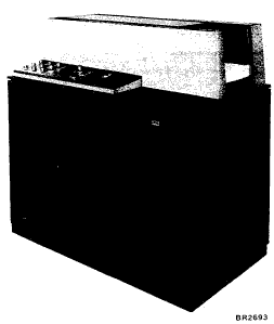
Figure 62. IBM 1231 Optical Mark Page Reader
The IBM 1231 Optical Mark Page Reader (OMPR) represents a breakthrough in source recording and data entry. The OMPR provides a facility for recording the data at its source, in a form that can be read directly into the IBM 1130 Computing System.

Figure 62. IBM 1231 Optical Mark Page Reader
The 1231 (Figure 62) reads positional marks made by an ordinary lead pencil on paper documents. The positional marks are read directly into the IBM 1130 core storage.
Documents are read at a maximum rate of 2,000 sheets per hour.
The document used as input to the Optical Mark Page Reader is an 8-½" x 11" sheet of paper called a "data sheet." The data sheet contains a maximum of 1,000 mark positions. The mark positions are arranged in an many as 50 rows, each row containing a maximum of 20 mark positions.
Each row is divided into two groups of ten mark positions each. The ten mark positions are called "words." Each word is divided into two groups of five mark positions called "segments." Consequently, each data sheet can have a maximum of 50 rows, 100 words, and 200 segments. A data sheet normally contains five rows per inch but may have less.
Timing marks are printed along the right-hand edge of each data sheet. These marks are used to synchronize the motion of the document with the sensing unit of the reader. Each word on the data sheet has an associated timing mark. For forms design information see the System Reference Library publication IBM 1231, 1232 Optical Mark Page Readers (Order No. GA21-9012).
Timing Mark: A rectangular mark preprinted on the data sheet in non-reflective ink. The timing mark is used to synchronize the motion of the document with the sensing unit of the 1231. Timing marks are located on the right-hand side of the data sheet.
Mark Positions: Areas printed in reflective ink that designate where marks are to be placed. A non-reflective mark in this area is read as a word or bit.
Word: Ten mark positions of a row. Words on the left half of the data sheet are odd words; words on the right half of the data sheet are even words.
Segments: Mark positions 0 through 4 and 10 through 14, or 5 through 9 and 15 through 19, of any word.
Non-Reflective Ink: A type of ink that is sensed by the 1231. Usually, timing marks are the only non-reflective printing on the data sheet. The recommended non-reflective ink is black.
Reflective Ink: A type of ink not sensed by the 1231. Reflective inks are used for headings, data sheet instructions, mark position outlines and any other data that is not to be read.
Marks that are to be read by the IBM 1231 must be dark enough for positive machine reading, yet erase easily and completely. For these reasons, a number 2 pencil is recommended.
Marks made with a number 1 pencil, or an IBM ELECTROGRAPHIC ® pencil are difficult to erase. Even after an erasure is made a residue remains that could be read as a mark by the machine.
Erasures should always be made carefully and completely. Any incomplete erasure could be read as a mark.
When response positions are marked, the mark should be made the full length of the mark position, and should fill at least two-thirds of the space between the top and bottom of the guide lines. A mark that extends no more than 1/16 inch past the ends of the response position is acceptable in all but the last even-word position (next to the timing marks). In this position, a mark must not extend beyond the right end of the guide lines or it could be read as a timing mark. This would result in erroneous reading of the rest of the data sheet.
The 1231 uses sonic delay lines for storing controls and data. Controls are marked on the regular data sheet and entered into delay line storage during the program load cycle. This data sheet is referred to as a program control sheet. The program control sheet is automatically placed in the select (upper) stacker during the load cycle.
As data sheets are read, data is stored in the delay lines according to instructions from the program control sheet. Each word to be stored on the delay line must be programmed by the program control sheet.
When a data sheet passes under the photoelectric read head, each word is tested for conditions, such as no-mark, multi-mark, or other-than-one. Switches on the 1231 control panel in conjunction with the program control sheet control the test of these conditions. Any word that does not pass the requirements of the switch settings causes the data sheet to be routed to the select stacker.
The data sheet begins its movement through the optical mark page reader when it is fed from the hopper by CPU program control. The document then passes under a read head and is next transported through the transport area, past a selection station, and on into one of the two gravity stackers.
Each word transferred from the 1231 to the 1130 reads into a single position of core storage. Words are transferred one segment at a time to the A buffer and the B buffer in the attachment; all odd segments (A buffer) enter positions 0-4 and 14, and all even segments (B buffer) enter positions 5-9 and 15 (Figure 63). If the 1231 is programmed for only one segment, all segments enter positions 04 and 14. Words with marks in positions 0, 1, 2, 3 or 4 transfer to core storage as an odd segment and marks in positions 5, 6, 7, 8, or 9 transfer to the 1130 as an even segment. Combinations of the bits make up a valid character which must be translated by the 1130 stored program. Any or all of the marking positions on the data sheet may contain marks.
Data is read by the 1231 from left to right, top to bottom, a row at a time. Information from a data sheet is stored in the following sequence:
If only one segment of any word is programmed to read, then each segment goes into a separate core storage word.
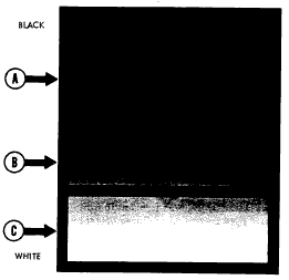
During the reading of data sheets, the Optical Mark Page Readers categorize marks according to their degree of light reflectance (Figure 64). A mark falls into one of the following categories:
A good mark is recognized as a positive indication of a mark; a poor mark (or good erasure) is not recognized as a mark, and an uncertain mark (light mark or poor erasure) is one whose light reflectance level comes somewhere in between a good mark and a poor mark but cannot be positively identified as either. The reading or rejection of uncertainties can be customer-controlled.

Figure 63. 1231 Data Format

Figure 64. Mark Reflectance Relationship
Three read-mode switches, each associated with a set of field-checking switches, allow operator control of mark discrimination on a field-by-field basis. Documents containing uncertainties can be selected for a visual check if desired.
Each of the three read-mode switches has four settings: SING RESP (single response), MULT RESP (multiple response), SING RESP SEL UNC (single response select uncertainties), MULT RESP SEL UNC (multiple response select uncertainties).
The setting of each read-mode switch affects mark discrimination as follows:
*Number of mark positions included in any one mark discrimination test is determined by the setting SEGMENT or WORD of the check-length switch.
Whenever a data sheet is selected by the 1231, storage is cleared and data from that data sheet is prevented from being transferred to the computer.
Before the 1231 can act as an input device to a data processing system, the controls for the internal functions must be loaded and switches must be set to establish the conditions required for the particular run.
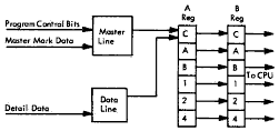
Two storage devices (sonic delay lines) are used to store and control the data as it is read from the data sheets. One of these storage devices, the "master" line, is used to store all the controls from the program control sheet. If the 1231 is equipped with the master mark special feature then master-mark data and controls associated with master-mark data are also stored.
The other storage line, the data line, is used to store information from the data sheet. As the data sheet is read, the two storage lines work concurrently and in synchronism. The master line, which contains the program instructions, determines which information from the data sheet is to be retained.
The following sequence is used for entering data into a fully equipped 1231 and for making this information available to the processing system (Figure 65).

Figure 65. IBM 1231 Data Flow
In field checking, each word programmed to be read is checked for mark conditions which may indicate invalid data. Three switch-controllable mark conditions, each of which will cause the document to be selected, can be checked. These conditions are: multi-marks, no marks, or other-than-one. The switch also has an off position.
Data sheets are usually designed with "fields" of similar data in vertically consecutive words on the left or right sides of the data sheet.
A field checking field differs from a data sheet field primarily in functional grouping. A data sheet field groups similar information for ease of marking and reference. A field checking field may contain part of, or several, data sheet fields. The primary requirement of field checking is that all mark data within a field's area of coverage be checked for the same conditions (multi-mark, no mark, etc.).
The field checking fields on the data sheet are defined by special codes (start-of-checking codes) which are entered into 1231 storage from the program control sheet. A field checking field can be from 1 to 100 words in length.
Three start-of-checking control codes allow any specific area of the data sheet to be checked according to one of three groups of field checking switches. The three groups of field checking switches are labeled, field I, field II, and field III.
The checking of a field checking field by a particular group of switches begins on the word in which the field checking control code is recognized. On the program control sheet, a mark in position 6 designates the start of data checking according to conditions set up on field I switches; a mark in position 7 designates the start of data checking according to conditions set up in field II switches; marks in positions 6 and 7 designate the start of data checking according to field III switches.
Three switches are assigned to each field: (1) a read mode switch, which determines how uncertain marks are handled, (2) a check length switch, which determines whether information is to be checked on a word or segment basis, and (3) a select condition switch, which determines the conditions for which a data sheet will be selected.
Because the data sheet is read from left to right, top to bottom, row by row, field checking becomes an important factor when a new data sheet is to be designed. If, for instance, the data sheet is to be used for a yes or no survey, the yes and no mark positions should be within one segment or word in order to allow checking for both, either, or neither answer.
The field checking feature can be summarized as follows:
When the data sheet is selected because of a field checking condition, or because of an uncertain reading, the 1231 causes the delay line to be reset. Some data may have been transferred. This data is considered to be invalid.
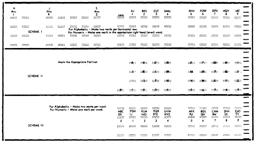
An alphabetic coding capability is necessary and desirable in many applications. Three schemes of alphabetic coding are illustrated in Figure 66.
Scheme 1: To code an alphabetic character, a mark must appear in the appropriate marking position of both the odd (left hand) and even (right hand) words of the same horizontal row. For example, to indicate the letter K, one mark must be made in the marking position immediately below the caption "J" through "R" in the odd word, and one mark must be made in the marking position immediately below the caption "BKS" in the even word of the same horizontal row. The odd word in this scheme represents the zone portion of the character.

Figure 66. Alphabetic Coding Schemes
Scheme 2: Each letter of the alphabet can be preprinted on the data sheet in reflective ink. The letters and/or numbers may be printed above, on, or below the mark positions. In this approach, the identity of each character is determined by its position in the matrix, which is programmable.
The entering of the marks is simple; however, considerable space is required on the data sheet to represent all the alphabetic and numeric characters.
Scheme 3: Each letter of the alphabet, or digits 0 through 9, can be represented by using only one word. An alphabetic character must be represented by a mark in each segment of the word selected for this purpose. (Z is an exception.) To indicate a K, marks in the 2-position of the left-hand segment and in the 5-position of the right-hand segment are required.
Programming for the IBM 1231 Optical Mark Page Reader depends upon two sources of control: controls stored within the 1231 and controls received from the 1130. Controls stored within the reader are entered into storage from a program control sheet.
A program control sheet is a data sheet with certain operational controls marked in the data areas. Each word from the data sheet consists of ten positions. Each word in the delay line storage consists of 16 positions: ten for the positions on the data sheet, and six for storing operational and internal controls generated by circuitry of the 1231.
Every word that is to be retained for transferral to the 1130 must have an operational control marked in that word on the program control sheet. When operational control - information is entered into storage, the controls go into some of the six control positions associated with each word.
During the program load cycle, the mark positions used as control positions are:
Three I/O commands are used with the 1231: control (100), read (010), and sense device (111). In addition the control command uses three modifier bits to expand the number of commands.
The 1231 is addressed by the five-digit device code (01000 = area code 8).
Control (100)![]()
This control command uses three modifier bits:
Read Start (bit 13): Causes the document to move through the read station. Data is collected and placed on the delay line controlled by the control sheet and switch settings. As soon as the first word programmed for output is placed on the delay line, it is made available to the processor.
I/O Disconnect (bit 14): Terminates the read operation from the document and clears the delay line storage by signaling the 1231 that no more data is desired. This command should be given to prevent a read (overrun) error on the next document if all data from the previous document is not cleared from the delay line storage.
Select Stacker (bit 8): Causes the document just read to enter the select stacker. This command can be given within 40 ms after the last word is placed on the delay line. Indicator bit 5 in the device status word is on if it is permissible to select the document. This bit should be tested prior to issuing the select command. If the bit is off and a command is issued the command will be ignored.
Read (010)![]()
This command causes the next word in the 1231 attachment buffer to be loaded into the core storage location specified by the address.
Sense Device (111)![]()
The sense device command causes the 1231 DSW (Figure 67) to be placed in the accumulator. Modifier bit 15 resets the responses.
Figure 67. 1231 Device Status Word
It is possible to read the last character of a document and receive the end of transmission signal from the 1231 before the timing mark check is made if the timing mark switch is set to yes. This would turn on the operation complete interrupt, which would then be serviced by the processor. If the timing mark switch were set to YES, a timing mark error could occur after the operation complete routine. Were this to occur, the timing mark error indicator would be turned on. This indicator would remain on until the 1231 was placed in the ready state. The operator would be aware or this error either by program analysis or by visual inspection of the 1231 control panel.
Read Response (Interrupt): Bit 0 signals that a word (one or two segments) has been loaded in the 1231 attachment buffer and can be accepted by the CPU. An XIO sense DSW command with bit 15 turns off the read request and loads the 1231 DSW into the accumulator. An XIO read command is needed to turn off the read busy indicator and transfer the word to core storage.
Timing Mark Error (Interrupt): Bit 1 indicates there is a timing mark error. Timing mark error turns on the operation complete interrupt. The error is dependent upon the settings of two switches: tuning mark check switch and control timing mark switch. The timing mark check switch is an 11-position rotary switch. It has an off position and ten positions labeled 0 through 9. In the off position no checking is performed. If checking is desired, the switch is placed on the digit corresponding to the units value of the number of timing marks on the documents. The control timing mark switch has two positions labeled YES and NO. The no position is used for documents having the normal number of timing marks (100 or fewer); the yes position is used for documents having 106 timing marks.
Read Error (Interrupt): Bit 2 indicates that a parity error (even count) occurred, an overrun condition occurred, or that no bits were entered onto one of the delay lines with either a data sheet or a control sheet. The not ready and the operation complete interrupt is turned on. The delay line storage is cleared so that it is not necessary to give an I/O disconnect.
Master Data: Bit 3 indicates that data to be transferred is master data. A master data subroutine should place master data in a reserved area. The indicator does not come on if the master-mark switch is off.
Operation Complete (Interrupt): Bit 4 indicator is turned on by the end of transmission and signifies that the last word has been read by the CPU. It is also turned on by the timing mark error or read character error. It is turned off by an XIO sense device with bit 15 on.
Okay to Select: Bit 5 indicator comes on when a document read is initiated and remains on for 40 ms after the document has been read.
Feed Busy: Bit 6 indicator comes on when the XIO control command with modifier bit 13 is executed. It remains on until the first 1231 interrupt is turned off. Another start feed command should not be given while this indicator is on.
Document Selected: Bit 7 is caused by either a mark count reject or data uncertainty, according to the setting of the field checking switches and the program control sheet. It is turned off by an XIO sense device with bit 15 on. Document feeding is not inhibited. When this indicator is turned on the delay line storage is cleared of data and the transfer to the processor is terminated. The operator must be flagged by the program that this has happened. If the next feed command has been issued it will be necessary to refeed two documents. If the document selected indicator is turned on and serviced before the next feed command, only the top sheet in the select stacker should be processed. Data should not be processed if this indicator is on.
Test Timing Mark Check: Bit 8 indicator comes on just before the first character interrupt from the 1231 attachment and remains on for 90 ms after the last word has been placed on the delay line. If the control timing mark switch is set to YES, the timing mark check is not made until the end of the 90 ms period. If this indicator is to be tested, data processing should not take place until the indicator goes off.
Hopper Empty: Bit 9 indicates that the 1231 hopper is empty and turns on not ready.
Check Stop (Interrupt): Bit 10 indicates the 1231 has encountered: a double feed, a transport jam, a feed command given but the documents are not being fed, or the 1130 program has issued a start read command and a not ready condition occurs before the 1231 responds.
Note: Not ready and hopper empty bits may appear in the DSW when a read response interrupt is being serviced during processing of the last document. Read response interrupts will continue and data will be available after not ready and hopper empty occur. Check stop interrupt is blocked until the document has been read.
Read Busy: Bit 13 indicates that the 1231 attachment buffer is full. It is turned off when the XIO read command for the 1231 is given.
Busy: Bit 14 indicator comes on after the read start command has been issued and remains on until an operation complete interrupt is received or an XIO disconnect command is issued. This indicator being on indicates that a document is being read.
Not Ready: Bit 15 indicator is off if the 1231 is ready to accept instructions from the CPU program. The following conditions are necessary for the 1231 to remain in a ready condition:
This meter runs when both of the following conditions are present:
The meter continues to run simultaneously with the 1131 meter until either the 1231 hopper becomes empty or it is stopped by the operator.
But wait, there's MORE...