
This section is provided for those who require an understanding of the 1130 CPU interrupt scheme. Normally, application programs (used in conjunction with the facilities of IBM-supplied programming systems for the 1130) interact with the 1130 CPU interrupt scheme by means of subroutines. Subroutines are supplied by IBM for the 1130, or they may be written by the application programmer. If IBM-supplied subroutines are used, it may not be necessary for the programmer to understand how the interrupt scheme is implemented in the 1130 CPU.
The temporary stopping of the current program routine, in order to execute some higher priority I/O subroutine, is called an interrupt. The interrupt mechanism in the CPU forces a branch out of the current program routine to one of several subroutines, depending upon which level of interrupt occurs.
I/O operations are started as a result of the execution of a program instruction. Once started, the I/O device continues its operation at the same time that the job program is being executed. Eventually the I/O operation reaches a point at which a program routine that is related to the I/O operation must be executed. At that point an interrupt is requested by the I/O device involved. The interrupt action results in a forced branch to the required subroutine.
In addition to the routine needed to start an I/O operation, subroutines are required to:
Note: Some I/O devices do not require program-instruction handling of data transfers to or from core storage. These devices are described in subsequent sections of this book. Their method of transferring data is called cycle steal and is not related to the interrupt program-subroutine method of handling data described in this section.
In order to understand the interrupt scheme, first examine the start of an I/O operation. Then contrast this operation with an interrupt occurrence, which in many respects is similar to the beginning of the I/O operation.
Shown in the following diagram are:

Branching from the job routine to the I/O routine occurs at point A in the diagram. This branch is a program-controlled operation that is started because the job program is at a point at which the I/O operation is required (such as the reading of a card in the card reader). Similarly, when the end of the I/O routine is reached, a program-controlled branch is made back to the job routine (point B). (Program-controlled means that the logical point at which the branch occurs is determined by the program; no forcing is performed by the CPU.)
Because the CPU can execute only one instruction at a time, the I/O routine and the job routine are not overlapped.
But the I/O device operation is overlapped with program-instruction execution because the I/O device can perform its functions without using the CPU mechanism required for execution of program instructions. In other words, the I/O device operation, once started, continues while program-instruction execution takes place in the CPU.
In summary, the important points to notice about starting the I/O operation are:
Assume that the I/O device in operation is the card reader (1442). The I/O device operation that has been started, then, is the moving of a card past the read station.

As soon as the card is moved far enough for one card column to be read, the card reader signals the CPU. This signal to the CPU is an interrupt request. The interrupt, however, does not occur until execution of the current instruction is completed. At that time, a forced branch occurs to an interrupt-handling subroutine.
The interrupt action can be shown pictorially in the following way:
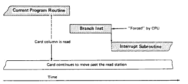
Logical requirements of the interrupt subroutine are carried out before a return to the interrupted program.
To return to the program routine that was in progress before the interrupt occurred, another branch must be provided. This, however, is a program-controlled branch and, therefore, is not forced by the CPU.
In summary,
As discussed, the two ways of branching into an I/O routine are:
In a program-controlled branch to an I/O routine, a properly written program has address information for the branch-to location and the return address, if needed. Similarly, when a CPU-forced branch occurs, a way must be provided to branch to the proper subroutine and return (via another branch) to the interrupted program at the end of the subroutine. Therefore, the following information must be available.
But at the time of the actual interrupt (after the current instruction is completely executed) the address of the next instruction is in the instruction-address register. (The next instruction is the one that would have been executed if the interrupt had not occurred.)
The next instruction address is stored into the first word of the interrupt-subroutine location. Storing is performed during execution of the CPU-forced branch at the time of the interrupt. The CPU-forced branch is a branch-and-store-IAR instruction (a BSI instruction). Format of this forced branch instruction is:

The beginning (first word) of the interrupt subroutine is specified by an address in the interrupt-vector location, which is the location that contains the effective address used during execution of the BSI instruction. The address field in the BSI instruction points to the interrupt vector. There are several interrupt-vector, fixed locations in core storage because there are several levels of interrupt. Interrupt levels and their associated vector locations are:
| Interrupt Level | Interrupt Vector Location (in core storage) |
Device | ||
|---|---|---|---|---|
| 0 | 00008 (in decimal) | 1442 Card Read Punch (column read, punch) | ||
| 1 | 00009 | 1132 Printer, synchronous communications adapter | ||
| 2 | 00010 | Disk storage, storage access channel | ||
| 3 | 00011 | 1627 Plotter, 2250 Display Unit, storage access channel, System/7 | ||
| 4 | 00012 | 1442 (operation complete), keyboard, console printer, 1134 Paper Tape Reader, 1055 Paper Tape Punch, 2501 Card Reader, 1403 Printer, 1231 Optical Mark Page Reader, storage access channel | ||
| 5 | 00013 | Console (program stop switch and interrupt run), storage access channel |
Suppose that an interrupt occurs at level 0. For this example, the address of the next instruction in the current program is 0502. This value (0502) is in the instruction-address register (IAR) when the CPU-forced branch occurs. Because the interrupt is at level 0, the CPU forces execution of the following branch instruction.

Execution of this instruction stores the contents (0502) of the instruction-address register into the first word location of the interrupt subroutine. The contents are kept there until needed for branching back to the interrupted program after the interrupt has been handled.
The first word of the interrupt subroutine is at the core-storage location specified by the contents of location 0008 (the interrupt-vector location for level 0). When the program is originally loaded into the system, the appropriate subroutine addresses must be stored (via program control) into the interrupt vectors. Therefore, for this example, the contents of core-storage location 0008 are 0600. Core-storage address 0600 is the address of the first word of the interrupt subroutine for interrupt-level 0. For this example, then, execution of the branch-and-store-IAR (the CPU-forced branch) results in:
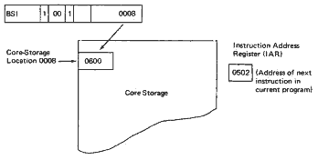
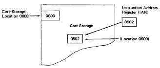
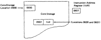
The interrupt subroutine must save the contents of certain index and machine registers (by storing their contents into core storage) before such registers are used for data manipulation within the subroutine. Only the contents of those registers that are used by the subroutine need be saved. The data integrity of such registers must be maintained because the interrupted program may use the same registers. At the end of the interrupt subroutine, the contents of the affected registers are loaded back into the registers from core storage.
For example, the accumulator is used by all subroutines. Therefore, the contents of the accumulator must be stored into core storage before the accumulator is used by the subroutine. At the end of the subroutine, before a return to the interrupted program, the accumulator is loaded with the data that is saved.
In general, two methods are used to determine what condition is causing an interrupt:
The I/O device causing an interrupt can be determined by examination (via programming) of the interrupt-level status word, when necessary. (The following discussion indicates when this is not necessary.) Then, after the device is known, the device-status word is examined to determine the condition in the device that caused the interrupt to occur.
First consider a level-O interrupt. An interrupt-level status word is not used at level 0. Only the device status word need be examined at interrupt level 0.
Either one of two conditions can cause level-0 interrupt to occur:
Because the 1442 can perform only a read or a punch operation at any one time, an interrupt at level 0 is for either a read or a punch operation. The program must determine which operation occurs. Clearly, sending a data word from core storage to the card punch during a read operation would be inappropriate.
Determination of whether the reader or the punch caused the level-0 interrupt is done in the following way: An execute I/O instruction addresses a sense-device I/O control command. Execution of this command, which specifically addresses the 1442, results in the loading of the 1442 device status word into the accumulator. Also, bit 15 in the second word of the command is on (that is, equals a value of 1). That bit, when on, causes a reset of the interrupt response. (The interrupt response is the signal, from the 1442, that originally requested the level-0 interrupt.)
Bits 0 and 1 of the 1442 device status word specify which operation (punch or read) causes the level-0 interrupt.

After the subroutine determines whether the interrupt is for a read or punch response, the appropriate action is taken:
At the end of the level-0 interrupt subroutine:
Interrupt-level stats words are defined for interrupt levels 1, 2, 3, 4, and 5. During execution of the subroutine, the interrupt-level status word for the level of interrupt can be put into the accumulator by an execute I/O instruction and sense-interrupt command. The contents of the interrupt level status words at the various interrupt levels are:

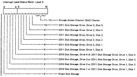
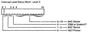
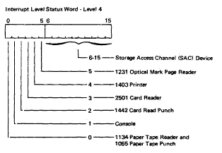
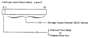
After an interrupt-level status word is loaded into the accumulator, the contents of that word can be inspected to determine the device causing the interrupt. For example, the procedure for level 1, for either the 1132 printer or the synchronous communications adapter, involves branching on the contents of the accumulator. If the value in the accumulator is negative (bit 0 set to a value of 1), then the interrupt is for the 1132:
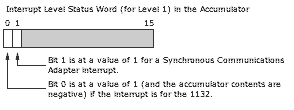
If bit 0 is not at a value of 1 during a level-1 interrupt, the interrupt must be for the synchronous communications adapter because that is the only other device that can cause an interrupt at level 1.
After the device causing the interrupt has been determined, a sense-device-status command can be executed (via an execute I/O instruction) to determine the condition within the device that caused the interrupt.
Figure 17 contains a sample interrupt-recognition routine.
Programming for level-5 interrupts is different from normal interrupt programming. The major difference for level 5 is the reset function in the sense-device-status-word command.
Program stop. The normally generated branch-and-store-instruction-address-register instruction (BSI) is performed with an indirect branch via storage-location OOOD (0013 in decimal). The execute I/O and sense DSW sequence is then performed to determine what caused the interrupt.
At completion of the branch-out at the end of the routine (a BOSC) another level-5 interrupt is requested, as if the program stop key were operated again. The request remains active until the start key or the reset key is operated to turn off the program-stop interrupt request.
Interrupt Run Mode. The normally generated branch-and-store-instruction-address-register instruction (BSI) is performed with an indirect branch via storage location OOOD (0013 in decimal). The execute I/O and sense DSW sequence is then performed to determine what caused the interrupt. The branch-out at the end of the routine (a BOSC) resets level-5 interrupt request and level-5 priority.
Interrupts at level 5 do not occur during other interrupt service routines. Therefore, interrupt routines cannot be traced.
|
Sample Interrupt Recognition Procedure The notes that follow, are numbered to correspond to the reference numbers in the procedure. Each reference number cited in text is circled, e.g., In the registers, instructions, and data words, only the necessary 0-bits and 1-bits are shown. Op codes are shown in alphabetic symbols, and decimal numbers are used to identify memory locations. Binary notation, where used, is obvious. IAR, ACC, ond XR1 are shown only where needed for understanding of the operation. |
|
|
|
Figure 17. Sample Interrupt Recognition Program
But wait, there's MORE...