The 1130 CPU instruction set is made up of five general classes of instructions:
Names, assembler mnemonics, and execution times of the instructions are listed in Figure 15.
The execution times can be used by the programmer to calculate whether time-dependent functions can be performed -- for example, whether there is sufficient time to execute a specific series of instructions between the time that an input record is stored in core storage until the next record from the same device is stored in core storage. Similarly, the execution times are used to calculate which one of two or more equivalent series of instructions (for example, two or more equivalent loops) can be executed faster, thus contributing to decreased program execution time.
| Instruction | Mnemonic | Binary OP Code | 1131 Models 1 and 2 Execution Times (in microseconds) | |||||||
|---|---|---|---|---|---|---|---|---|---|---|
| Single Word (F = 0) | Double Word (F = 1) | |||||||||
| T = 00 | T = 01, 10, or 11 | T = 00 | T = 01. 1O, or 11 | |||||||
| Avg. | Max. | Avg. | Max. | Avg.1 | Max.1 | Avg.1 | Max.1 | |||
| Load and Store | ||||||||||
| Load ACC | LD | 11000 | 7.6 | -- | 11.2 | -- | 10.8 | -- | 14.8 | -- |
| Load Double | LDD | 11001 | 11.2 | -- | 14.9 | -- | 14.4 | -- | 18.0 | -- |
| Store ACC | STO | 11010 | 7.6 | -- | 11.2 | -- | 10.8 | -- | 14.8 | -- |
| Store Double | STD | 11011 | 11.2 | -- | 14.9 | -- | 14.4 | -- | 18.0 | -- |
| Load Index | LDX | 01100 | 4.5 | -- | 7.2 | -- | 7.2 | -- | 11.8 | -- |
| Store Index | STX | 01101 | 7.6 | -- | 11.2 | -- | 11.8 | -- | 15.4 | -- |
| Load Status | LDS7 | 00100 | 3.6 | -- | 3.6 | -- | -- | -- | -- | -- |
| Store Status | STS | 00101 | 7.6 | -- | 11.2 | -- | 10.8 | -- | 14.8 | -- |
| Arithmetic | ||||||||||
| Add | A | 10000 | 8.0 | 13.0 | 11.7 | 16.6 | 11.2 | 16.2 | 15.3 | 20.3 |
| Add Double | AD | 10001 | 12.2 | 22.0 | 15.8 | 25.6 | 15.3 | 25.2 | 19.3 | 29.5 |
| Subtract | S | 10010 | 8.0 | 13.0 | 11.7 | 16.6 | 11.2 | 16.2 | 15.3 | 20.3 |
| Subtract Double | SD | 10011 | 12.2 | 22.0 | 15.8 | 25.6 | 15.3 | 25.2 | 19.3 | 29.5 |
| Multiply | M | 10100 | 25.7 | 40.0 | 29.3 | 43.6 | 29.3 | 43.6 | 32.9 | 47.2 |
| Divide | D | 10101 | 76.0 | 150.8 | 79.6 | 154.4 | 79.6 | 154.4 | 83.2 | 150.0 |
| AND | AND | 11100 | 7.6 | -- | 11.2 | -- | 10.8 | -- | 14.8 | -- |
| OR | OR | 11101 | 7.6 | -- | 11.2 | -- | 10.8 | -- | 14.8 | -- |
| Exclusive OR | EOR | 11110 | 7.6 | -- | 11.2 | -- | 10.8 | -- | 14.8 | -- |
| Shift Left*, Modifier Bits 8 & 9 | ||||||||||
| No Operation | NOP | 00010 | 3.6 | -- | -- | -- | -- | -- | -- | -- |
| Shift Left Acc,00 | SLA7 | 00010 | 3 | -- | 4 | -- | -- | -- | -- | -- |
| Shift Left ACC and EXT,10 | SLT7 | 00010 | ||||||||
| Shift Left and Count ACC,01 |
SLCA7 8 | 00010 | ||||||||
| Shift Left and Count ACC and EXT,11 |
SLC7 8 | 00010 | ||||||||
| Shift Right*,Modifier Bits 8 & 9 |
||||||||||
| Shift Right ACC,OO or O1 | SRA7 | 00011 | ||||||||
| Shift Right ACC and EXT,10 |
SRT7 | 00011 | ||||||||
| Rotate Right,11 | RTE7 | 00011 | 5 | 6 | ||||||
| Branch | ||||||||||
| Branch and Store IAR | BSI | 01000 | 7.6 | -- | 11.2 | -- | 10.82 | -- | 14.8 | -- |
| Branch or Skip on Condition | BSC | 01001 | 3.6 | -- | 3.6 | -- | 7.22 | -- | 11.2 | -- |
| Modify Index and Skip | MDX | 01110 | 4.5 | 9.9 | 11.2 | 16.2 | 18.5 | 23.4 | 18.5 | 23.4 |
| Wait | WAIT7 | 0O11O9 | 3.6 | -- | 3.6 | -- | -- | -- | -- | -- |
| Input/Output | ||||||||||
| Execute I/O | XIO10 | 00001 | 11.2 | -- | 14.8 | -- | 14.4 | -- | 18.4 | -- |
*Valid in short format only
Notes:
| 1. Indirect addressing, where applicable, adds one storage cycle (3.6 µsec) to execution time. | 6. N > 16: two storage cycles + 0.45(N-19). N < 16: two storage cycles +0.45(N-4). where N = number of positions shifted, When N = 16, only two storage cycles are used. |
| 2. If branch is taken. | |
| 3. One storage cycle + 0.45(N-4). When N ≤ 4, only one storage cycle is used. | 7. Indirect addressing not allowed. |
| 4. Two storage cycles + 0.45(N-4). When N ≤ 4, only two storage cycles are used. | 8. If T = 00. functions as SLA or SLT. |
| 9. All unassigned OP codes are defined as wait operations. | |
| 5. N > 16: one storage cycle + 0.45(N-19). N < 16: one storage cycle + 0.45(N-4). When N 16. only one storage cycle is used. |
10. If XIO read or write, add one storage cycle. |
Figure 15 (Part 1 of 3). 1130 Instruction Set and Execution Times
| Instruction | Mnemonic | Binary OP Code | 1131 Models 3 and 5 Execution Times (in microseconds) | |||||||
|---|---|---|---|---|---|---|---|---|---|---|
| Single Word (F = 0) | Double Word (F = 1) | |||||||||
| T = 00 | T = 01, 10, or 11 | T = 00 | T = 01. 1O, or 11 | |||||||
| Avg. | Max. | Avg. | Max. | Avg.1 | Max.1 | Avg.1 | Max.1 | |||
| Load and Store | ||||||||||
| Load ACC | LD | 11000 | 4.6 | -- | 6.8 | -- | 6.6 | -- | 9.0 | -- |
| Load Double | LDD | 11001 | 6.8 | -- | 9.1 | -- | 8.8 | -- | 11.0 | -- |
| Store ACC | STO | 11010 | 4.6 | -- | 6.8 | -- | 6.6 | -- | 9.0 | -- |
| Store Double | STD | 11011 | 6.8 | -- | 9.1 | -- | 8.8 | -- | 11.0 | -- |
| Load Index | LDX | 01100 | 2.7 | -- | 4.4 | -- | 4.4 | -- | 7.2 | -- |
| Store Index | STX | 01101 | 4.6 | -- | 6.8 | -- | 7.2 | -- | 9.4 | -- |
| Load Status | LDS7 | 00100 | 2.2 | -- | 2.2 | -- | -- | -- | -- | -- |
| Store Status | STS | 00101 | 4.6 | -- | 6.8 | -- | 6.6 | -- | 9.0 | -- |
| Arithmetic | ||||||||||
| Add | A | 10000 | 4.9 | 7.9 | 7.1 | 10.1 | 6.8 | 9.9 | 9.4 | 12.4 |
| Add Double | AD | 10001 | 7.5 | 13.4 | 9.6 | 15.6 | 9.4 | 15.4 | 11.8 | 18.0 |
| Subtract | S | 10010 | 4.9 | 7.9 | 7.1 | 10.1 | 6.8 | 9.9 | 9.4 | 12.4 |
| Subtract Double | SD | 10011 | 7.5 | 13.4 | 9.6 | 15.6 | 9.4 | 15.4 | 20.1 | 26.1 |
| Multiply | M | 10100 | 15.7 | 24.4 | 17.9 | 26.6 | 17.9 | 26.6 | 18.8 | 28.8 |
| Divide | D | 10101 | 46.4 | 92.1 | 48.6 | 94.4 | 48.6 | 94.4 | 50.8 | 91.6 |
| AND | AND | 11100 | 4.6 | -- | 6.8 | -- | 6.6 | -- | 9.0 | -- |
| OR | OR | 11101 | 4.6 | -- | 6.8 | -- | 6.6 | -- | 9.0 | -- |
| Exclusive OR | EOR | 11110 | 4.6 | -- | 6.8 | -- | 6.6 | -- | 9.0 | -- |
| Shift Left*, Modifier Bits 8 & 9 | ||||||||||
| No Operation | NOP | 00010 | 2.2 | -- | -- | -- | -- | -- | -- | -- |
| Shift Left Acc,00 | SLA7 | 00010 | 3 | -- | 4 | -- | -- | -- | -- | -- |
| Shift Left ACC and EXT,10 | SLT7 | 00010 | ||||||||
| Shift Left and Count ACC,01 |
SLCA7 8 | 00010 | ||||||||
| Shift Left and Count ACC and EXT,11 |
SLC7 8 | 00010 | ||||||||
| Shift Right*,Modifier Bits 8 & 9 |
||||||||||
| Shift Right ACC,OO or O1 | SRA7 | 00011 | ||||||||
| Shift Right ACC and EXT,10 |
SRT7 | 00011 | ||||||||
| Rotate Right,11 | RTE7 | 00011 | 5 | 6 | ||||||
| Branch | ||||||||||
| Branch and Store IAR | BSI | 01000 | 4.6 | -- | 6.8 | -- | 6.62 | -- | 9.0 | -- |
| Branch or Skip on Condition | BSC | 01001 | 2.2 | -- | 2.2 | -- | 4.42 | -- | 6.8 | -- |
| Modify Index and Skip | MDX | 01110 | 2.7 | 6.0 | 6.8 | 9.9 | 11.3 | 14.3 | 11.3 | 14.3 |
| Wait | WAIT7 | 0O11O9 | 2.2 | -- | 2.2 | -- | -- | -- | -- | -- |
| Input/Output | ||||||||||
| Execute I/O | XIO10 | 00001 | 6.8 | -- | 9.0 | -- | 8.8 | -- | 11.2 | -- |
*Valid in short format only
Notes:
| 1. Indirect addressing, where applicable, adds one storage cycle (2.2 µsec) to execution time. | 6. N > 16: two storage cycles + 0.275(N-19). N < 16: two storage cycles +0.275(N-4). where N = number of positions shifted, When N = 16, only two storage cycles are used. |
| 2. If branch is taken. | |
| 3. One storage cycle + 0.275(N-4). When N ≤ 4, only one storage cycle is used. | 7. Indirect addressing not allowed. |
| 4. Two storage cycles + 0.275(N-4). When N ≤ 4, only two storage cycles are used. | 8. If T = 00. functions as SLA or SLT. |
| 9. All unassigned OP codes are defined as wait operations. | |
| 5. N > 16: one storage cycle + 0.275(N-19). N < 16: one storage cycle + 0.275(N-4). When N 16. only one storage cycle is used. |
10. If XIO read or write, add one storage cycle. |
Figure 15 (Part 2 of 3). 1130 Instruction Set and Execution Times
| Instruction | Mnemonic | Binary OP Code | 1131 Model 4 Execution Times (in microseconds)** | |||||||
|---|---|---|---|---|---|---|---|---|---|---|
| Single Word (F = 0) | Double Word (F = 1) | |||||||||
| T = 00 | T = 01, 10, or 11 | T = 00 | T = 01. 1O, or 11 | |||||||
| Avg. | Max. | Avg. | Max. | Avg.1 | Max.1 | Avg.1 | Max.1 | |||
| Load and Store | ||||||||||
| Load ACC | LD | 11000 | 12.1 | -- | 18.0 | -- | 17.5 | -- | 23.8 | -- |
| Load Double | LDD | 11001 | 18.0 | -- | 23.8 | -- | 23.4 | -- | 29.2 | -- |
| Store ACC | STO | 11010 | 12.1 | -- | 18.0 | -- | 17.5 | -- | 23.8 | -- |
| Store Double | STD | 11011 | 18.0 | -- | 23.8 | -- | 23.4 | -- | 29.2 | -- |
| Load Index | LDX | 01100 | 6.8 | -- | 11.7 | -- | 11.7 | -- | 18.5 | -- |
| Store Index | STX | 01101 | 12.1 | -- | 18.0 | -- | 18.5 | -- | 24.3 | -- |
| Load Status | LDS7 | 00100 | 5.9 | -- | 5.9 | -- | -- | -- | -- | -- |
| Store Status | STS | 00101 | 12.1 | -- | 18.0 | -- | 17.5 | -- | 23.8 | -- |
| Arithmetic | ||||||||||
| Add | A | 10000 | 12.6 | 19.8 | 18.4 | 25.6 | 18.0 | 25.2 | 24.3 | 31.5 |
| Add Double | AD | 10001 | 18.9 | 35.5 | 24.8 | 41.5 | 24.3 | 40.9 | 30.6 | 47.7 |
| Subtract | S | 10010 | 12.6 | 19.8 | 18.4 | 25.6 | 18.0 | 25.2 | 24.3 | 31.5 |
| Subtract Double | SD | 10011 | 18.9 | 35.5 | 24.8 | 41.5 | 24.3 | 40.9 | 30.6 | 47.7 |
| Multiply | M | 10100 | 41.4 | 64.8 | 47.5 | 70.6 | 47.5 | 70.6 | 53.1 | 76.5 |
| Divide | D | 10101 | 123.3 | 243.0 | 129.1 | 248.8 | 129.1 | 248.8 | 135.0 | 242.1 |
| AND | AND | 11100 | 12.1 | -- | 18.0 | -- | 17.5 | -- | 23.8 | -- |
| OR | OR | 11101 | 12.1 | -- | 18.0 | -- | 17.5 | -- | 23.8 | -- |
| Exclusive OR | EOR | 11110 | 12.1 | -- | 18.0 | -- | 17.5 | -- | 23.8 | -- |
| Shift Left*, Modifier Bits 8 & 9 | ||||||||||
| No Operation | NOP | 00010 | 5.9 | -- | -- | -- | -- | -- | -- | -- |
| Shift Left Acc,00 | SLA7 | 00010 | 3 | -- | 4 | -- | -- | -- | -- | -- |
| Shift Left ACC and EXT,10 | SLT7 | 00010 | ||||||||
| Shift Left and Count ACC,01 |
SLCA7 8 | 00010 | ||||||||
| Shift Left and Count ACC and EXT,11 |
SLC7 8 | 00010 | ||||||||
| Shift Right*,Modifier Bits 8 & 9 |
||||||||||
| Shift Right ACC,OO or O1 | SRA7 | 00011 | ||||||||
| Shift Right ACC and EXT,10 |
SRT7 | 00011 | ||||||||
| Rotate Right,11 | RTE7 | 00011 | 5 | 6 | ||||||
| Branch | ||||||||||
| Branch and Store IAR | BSI | 01000 | 12.1 | -- | 18.0 | -- | 17.52 | -- | 23.8 | -- |
| Branch or Skip on Condition | BSC | 01001 | 5.9 | -- | 5.9 | -- | 11.72 | -- | 18.0 | -- |
| Modify Index and Skip | MDX | 01110 | 6.8 | 14.4 | 18.0 | 25.2 | 29.6 | 36.9 | 29.6 | 36.9 |
| Wait | WAIT7 | 0O11O9 | 5.9 | -- | 5.9 | -- | -- | -- | -- | -- |
| Input/Output | ||||||||||
| Execute I/O | XIO10 | 00001 | 18.0 | -- | 23.8 | -- | 23.4 | -- | 25.9 | -- |
*Valid in short format only
**Execution times are the same as for Models 1 and 2 when either interruption level 0 or 1 is active.
Notes:
| 1. Indirect addressing, where applicable, adds one storage cycle (5.9 or 3.6 µsec) to execution time. | 6. N > 16: two storage cycles + 0.45(N-19). N < 16: two storage cycles +0.45(N-4). where N = number of positions shifted, When N = 16, only two storage cycles are used. |
| 2. If branch is taken. | |
| 3. One storage cycle + 0.45(N-4). When N ≤ 4, only one storage cycle is used. | 7. Indirect addressing not allowed. |
| 4. Two storage cycles + 0.45(N-4). When N ≤ 4, only two storage cycles are used. | 8. If T = 00. functions as SLA or SLT. |
| 9. All unassigned OP codes are defined as wait operations. | |
| 5. N > 16: one storage cycle + 0.45(N-19). N < 16: one storage cycle + 0.45(N-4). When N 16. only one storage cycle is used. |
10. If XIO read or write, add one storage cycle. |
Figure 15 (Part 3 of 3). 1130 Instruction Set and Execution Times
The following instruction descriptions generally include:
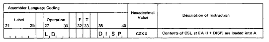
In this example, the contents of the core-storage location (CSL) specified by the effective address (EA), which is determined by the contents of the instruction address register (I) plus the displace ment (DISP), are loaded into the accumulator (A). The description is condensed through use of the abbreviated notation shown to the right of the hexadecimal value.
The symbols used in the instruction examples and the meanings of such symbols are:
| Symbol | Meaning |
| A | Accumulator |
| Q | Accumulator extension |
| ADDR or ADDRESS | Contents of the address field of a long-format instruction |
| CSL | Core-storage location |
| DISP | Contents of the displacement field in a short-format instruction |
| EA | Effective address (refer to "Effective-Address Generation") |
| EA + 1 | The next word location after the one specified by the EA |
| I | Contents of the instruction-address register |
| V | Value |
| XR1 | Contents of index-register I |
| XR2 | Contents of index-register 2 |
| XR3 | Contents of index-register 3 |
| X | Any valid hexadecimal digit |
Pictorial representations appear in the "Description" portion of text for most of the instructions. The purpose of these illustrations is merely to clarify the main points of the operations. They are not meant to present all the variations or exceptions that are discussed in the descriptive narrative. In the pictorial representations, the outlined numerals [omitted] simply point out the order of the steps within the illustration (not necessarily the order of steps within an instruction execution) so that you may follow the presentation more easily; these outlined numerals have no other purpose.
This manual does not present a detailed explanation of assembler-language coding. Rules of assembler-language coding are in IBM 1130 Assembler Language, Order No. GC26-5927, which should be used with this functional-characteristics manual whenever reference to assembler-language rules is required.
But wait, there's MORE...